Yamuna Highway

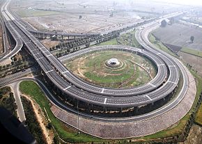
Fig: Aerial view of Yamuna Expressway

Fig: Aerial view of Yamuna Expressway

In 2012, OSD was involved in designing and implementing the network scheme at the 165.5km Yamuna Expressway, connecting the Indian cities, Noida and Agra via Mathura along the Yamuna River. The Yamuna Expressway is India’s Longest Access Controlled Concrete Pavement Expressway which features 4 control rooms. OSD products are used to provide the fiber optic backbone for the highway’s state of the art intelligent transport system (ITS).

The OSD860S was used to provide redundant real-time analogue and uncompressed digital fiber optic video links while the OSD2244 and OSD2700 were used to provide a redundant Gigabit Ethernet backbone along the highway supporting IP cameras, VIDS and VMS signals.

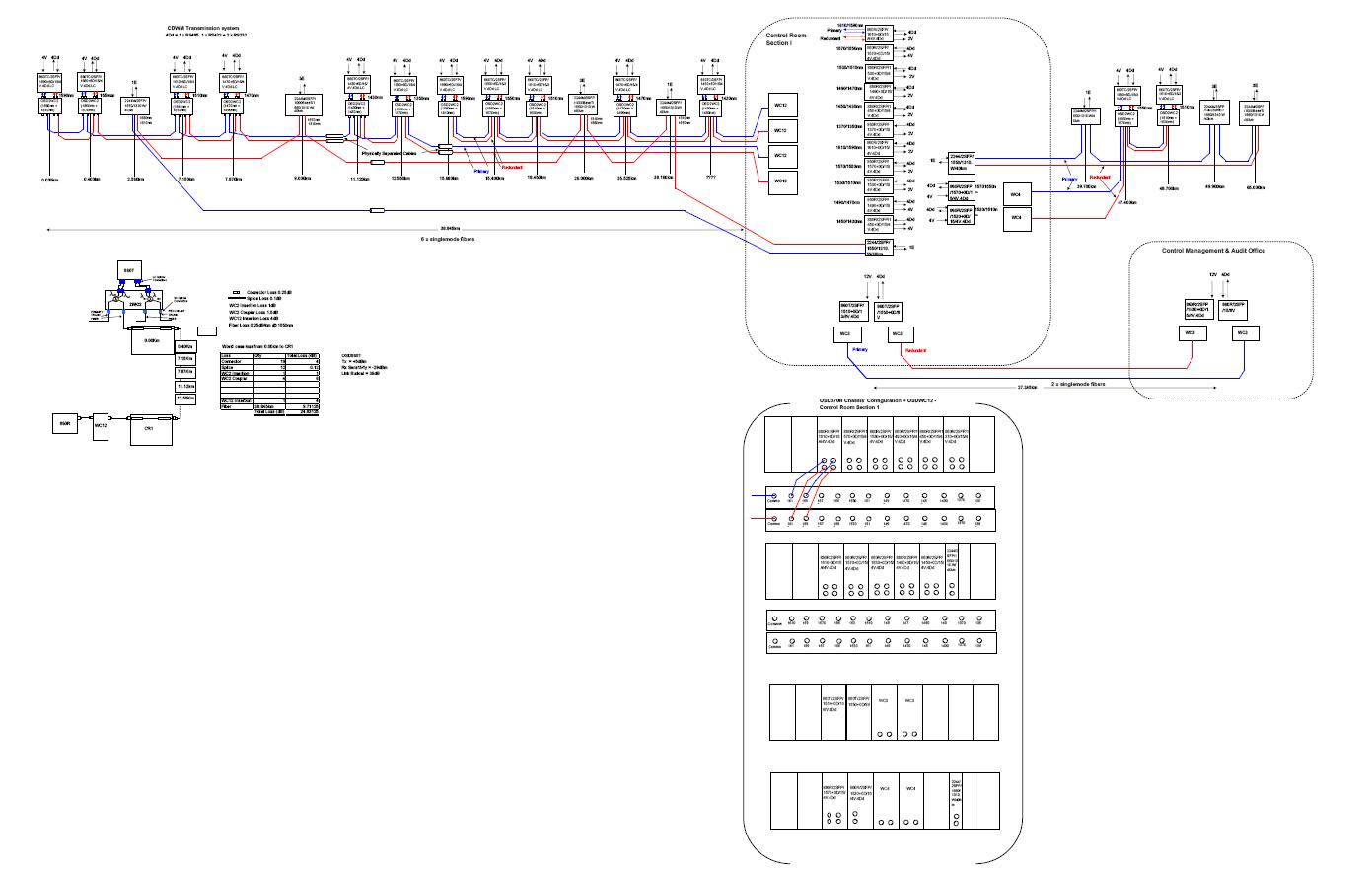
The ITS comprises of 3 sub-control rooms and a main control room. As well as providing the redundant fiber optic links from the field devices to the 3 sub-control rooms, OSD also provided the redundant  fiber optic links from each sub-control room to the main control room with the longest link is exceeding 135km. This was all achieved on minimal fibers using Course Wavelength Division Multiplexing (CWDM).

Yamuna Highway

Figure 2: Project Layout of Yamuna Expressway project

AM Vs FM Vs Digital Vs IP Video Transmission

There is some confusion in the marketplace as which technology is most appropriate for different applications.  While there is a lot of marketing hype about IP technology the fact remains that for many applications the “old fashioned” AM, FM or even Digital technologies offer anything from very adequate performance to stunning performance at extremely competitive pricing.  The following attempts to give a flavour of the trade offs between the main technologies available today.

Amplitude Modulation (AM) Systems

AM is a very simple technology which can provide extremely good performance for many situations.  It is easy to get wide bandwidths (at least 15MHz for our OSD381/383 pair, much more for some specialty products) without excessive circuit complexity.  Also, over low optical loss budgets typical of most security type CCTV which only occasionally operates over more than 2 to 3 km  the signal-to-noise ratio attainable with AM can be very good.  This does degrade from some maximum value (typically 55 to 70dB measured over a short fiber length) with increasing fiber length (and loss), so some care is required to ensure that your optical loss budget is under control.  However, linearity as measured by parameters such as differential gain and phase, while perfectly adequate for single hop CCTV links is not usually good enough for systems where 3 or 4 links may have to be put in for the series.  It can be difficult to achieve the linearity obtained with multimode AM systems on singlemode AM links because the optical devices required for the latter are usually not as linear as those for multimode.  Typically, OSD’s AM products can be considered very mature and are unlikely to be developed much further.  Having said that, several of them such as the OSD365A micro-miniature video transmitter and the OSD553 triple receiver cards continue to be very popular owing to their attractive combination of performance, cost and reliability.

Frequency Modulation (FM) Systems

FM has two key advantages over AM.

  1. Performance is not so strongly dependent on optical loss: the signal to noise ratio will degrade slowly with increasing loss to a threshold point after which it degrades very quickly.
  2. Performance is not dependent on the linearity of the optical components since it is almost completely dominated by the FM modulator and demodulator.

This improvement comes at a small cost of an increase in circuit complexity and cost and a large increase in fiber bandwidth required.  Generally the latter is not too critical but must be factored in if you are considering long runs on multimode fiber (e.g. greater than 10 to 20km) due to modal bandwidth limitations or even longer runs on singlemode fiber (eg greater than 30 to 100km) due to material dispersion effects.  OSD’s application engineers can advise on the best design choices in these cases.

Typically FM systems offer good SNR (60 to 65dB) which is maintained over substantial optical losses and good linearity which is typically 2 to 3 times better than AM.  Consequently, multiple loops become more practical.

However, FM occupies the middle ground between AM and Digital systems in terms of performance but is fairly comparable with Digital in terms of pricing.  Consequently, in new systems it tends to be mostly used in multimode systems operating over several kilometers where Digital is not technically practical because of the great demands it places on fiber bandwidth.

Digital Systems

“Digital” in this context refers to uncompressed digital transmission systems where the analog signal is digitised in an Analog to Digital Converter (ADC) and transmitted in serial form over the fiber at data rates from 100Mbps for fairly low performance products up to more than 300Mbps for high end products.  The system video performance is dominated by the analog to digital conversion at the transmit end and the digital to analog conversion at the receive end.  The actual transmission path will have virtually no visual effect on the picture if the Bit Error Rate is better than 1 error in 1 billion bits (ie a BER of 1 X 10⁻⁹).  In fact, BERs down to as low as 1 X 10⁻⁴ still allow quite useable signals to be received and monitored on screens.

These excellent characteristics come at the cost of:

  1. Increased circuit complexity and cost.
  2. Greatly increased transmission bandwidth requirements.

The basic SNR is determined by the number of quantization levels, which are in turn fixed by the number of bits per digital word.  Typically systems use between 8 and 12 bits leading to weighted SNR values of between about 56dB for 8bits and >70dB for 12 bits.

Be careful about the headroom allowed in digital systems: typically if you exceed the nominal level of AM and FM systems some distortion takes place but it may not be obvious.  Exceeding the limit in a digital system results in fairly obvious limiting effects.  Unlike its competitors, OSD includes an extra 3dB headroom in its input circuits to allow for out-of-specification cameras, matrix switches and distribution amplifiers which are often exist in the real world.  We achieve this by using ADCs which are specified at a very high level: for example our 10 bit products all use 12bit ADCs, even though we only transmit 10 bits over the fiber, to ensure true 10bit performance.  Likewise, our 9-bit products use 10 bit ADCs.

As noted earlier, digital systems require far more bandwidth than FM or AM systems.  For example, OSD’s 4 channel OSD870, 880 and 890 systems offer studio quality 10MHz video performance and the OSD860 8-channel system offers 6MHz bandwidth at a slightly lesser performance level with all of them operating on the fiber at 1.35Gbps.  This significantly reduces the distances achievable in multimode fiber: contact OSD Application Engineering for advice when using multimode or when transmitting more than 50km on singlemode fiber.

Internet Protocol (IP) Systems

The previous three technologies are often lumped under the generic term “analog systems” whereas systems based on IP transmission are often called “digital systems” so there can sometimes be confusion as to what people are referring to when talking about digital systems.

IP solutions typically involve the digitisation of an analog video signal then using some sort of compression to reduce the hundreds of megabits per second transmission rates referred to above down to data rates that can be easily transmitted over relatively low bandwidth media such as the Internet, corporate local networks or even leased lines.  The speeds available range from less than 10kbps to well over 10Mbps.  Clearly, the lower the speed the more compression is required and the lower the ultimate quality is likely to be.  There are many so-called “IP Cameras” available which are basically an analog camera with built-in digital compression which typically uses MPEG4 or H.264 encoding.  Most (not all) of these tend to have fairly average quality so the second way IP systems are implemented is to use a standard analog camera with a standalone encoder which, again, is usually MPEG4 or H.264.

The very best IP systems provide excellent subjective performance although very few actually measure very well (Please see “Video Quality”).  However, the main driver behind these systems is not picture quality but system convenience and control.  The fact that most organisations have an Ethernet Local Area Network (LAN) somewhere in the background means that (theoretically) one can place a camera wherever there is access to the LAN and connect it back to the security control center without the need to install any dedicated CCTV cabling.  Many possibilities arise once the pictures are on the network:

  1. Storage on multiple Network Video Recorders (NVR) is possible anywhere in the world
  2. Multiple display sites are possible
  3. Integration of CCTV with other aspects of security and organisational management such as access control, perimeter protection, building management systems, etc becomes practical

Despite these features, as of 2010 only about 30% of CCTV systems worldwide are IP based with many users preferring to maintain an analog camera and transmission system (although these will often employ uncompressed digital video systems such as OSD’s OSD8XX and OSD8XXX product ranges) and then perform all IP related functions at the security control center, usually via multi-channel Digital Video Recorders (DVR).

There is no question that with continual improvements in IP technology (LAN speed, compression techniques, storage technologies, etc) a majority of CCTV systems will be IP based by 2015.

Summary 

Most CCTV systems over the next several years will rely on so-called “analog” transmission technology whether it be AM, FM or Digital with a growing proportion becoming all IP.

The transmission can be AM in many simple applications because of its good performance at cost effective pricing.  AM can also be considered where long lengths of multimode cable must be covered.

Many multimode fiber based commercial and professional applications can be well served by FM based systems which can offer excellent video, audio and data performance but, in general, digital systems would be better, particularly if singlemode fiber is being used.

Overall, OSD would recommend digital systems for most applications where high performance or long distances are involved.  Digital systems can also be used over multimode fiber but be careful to consider multimode’s bandwidth limitations.

Finally, don’t hesitate to contact OSD if you would like some advice on any of these topics.
Multimode versus Singlemode

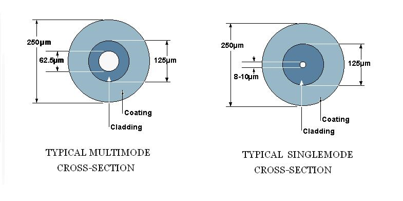
Figure 1: Cross-sections of Multimode and Singlemode fibers

Figure 1: Cross-sections of Multimode and Singlemode fibers

For many years now we at Optical Systems Design have been promoting the major technical and economic advantages of singlemode fiber versus multimode.

Very often, it unfortunately seems that typical singlemode equipment is much more expensive that the equivalent multimode gear.

However, as surprising as it may appear, the much higher performance singlemode fiber and cable has for at least 20 years been substantially lower cost than multimode primarily due to its simpler structure (resulting in faster manufacturing time) and its vastly greater volume of production.  Consequently, in the past there has often been a trade-off possible between the cost of singlemode gear and the lower cost of SM cable with the changeover point from a multimode system to a singlemode system typically occurring somewhere between 500 and  1500 meters.

This juggling act is finally becoming unnecessary: OSD’s latest range of digital video and Ethernet products are the same price for either fiber type so you get all the technical advantages of SM as cost effectively as MM.  Furthermore, we intend to continue with this trend for almost all new OSD products. You can expect to pay the same or less for a singlemode product as for the multimode version. Often, the product will, in fact, be the same unit: a major advantage when you have a legacy network with a mix of SM and MM fibers.

Video Quality

Have you ever noticed that when reading specifications for standard analog in/out transmission systems and those for video over IP systems the huge differences between what is, and what is not, specified?

Even the lowest cost fiber systems will provide basic information such as system bandwidth and signal-to-noise ratio (SNR) whereas IP systems rarely mention these or linearity figures such as differential gain (DG) and phase (DP) but will inform you that the picture is available as 4CIF down to QCIF at anything from 25 frames per second (fps) down to 1 fps or less.  There are a number of reasons for this but one most certainly is that if you actually measure a typical video over IP system using a standard television measurement system such as the Tektronix VM700 the numbers are usually pretty bad.  For example, a simple uncompressed digital video system such as OSD’s OSD8815 offers 10MHz bandwidth with a minimum SNR of 65dB and DG/DP of better than 0.7%/0.7º, numbers that only several years ago would have been considered better than broadcast quality.  On the other hand, typical video over IP systems provide 4 to 5MHz bandwidth, SNR of 40 to 45dB and almost immeasurably bad DG/DP figures.

Yet, the world is moving over to video over IP systems!

Why? Because these systems enable customers to use a common building infrastructure for security, access control and building management functions.  With great care these functions can even be carried over the same local area network system employed by the IT Department, thus potentially substantially cutting costs.  However, in most situations, it is still better to run separate cabling systems with their own horizontal wiring and vertical (backbone) wiring because video systems are very bandwidth hungry and even as few as 20 IP cameras can cause a perceptible slowdown of system throughput on networks with a 1Gbps Backbone, and would be impractical on 100Mbps Ethernet systems.  With the advent of economic 10 GBps Ethernet it is likely that some merging of the two systems will become more common.

While it is straightforward to measure the standard video parameters mentioned above using a wide variety of equipment available from scores of manufacturers, things become decidedly murkier when looking at video over IP.  One very basic reason is that after encoding it is normal for pictures to remain in compressed format right up to output to a flatscreen monitor so that an end-to-end measurement of an analog signal is often just not possible.  Another is that actually trying to objectively measure the quality of a compressed video in what could be one of hundreds of standards or variants of a standard is very difficult.  Consequently, until some standardisation occurs we are stuck with vague subjective statements such as “DVD quality” on many manufacturers’ datasheets.

There are better ways of measuring video quality but most are still subjective. For example, the Video Quality Expert Group (VQEG) has created a specification for subjective video quality testing and submitted it to the governing body as ITU-R BT.500 Recommendation. This recommendation describes methods for subjective video quality analysis where a group of human testers analyze the video sequence and grade the picture quality. The grades are combined, correlated and reported as Mean Opinion Score (MOS). The main idea can be summarized as follows:

  1. Choose video test sequences (known as SRC)
  2. Create a controlled test environment (known as HRC)
  3. Choose a test method (DSCQS SSCQE)
  4. Invite a sufficient number of human testers (20 or more)
  5. Carry out the testing
  6. Calculate the average score and scale

All of which is great for assessing a compression system but is not too practical for online performance monitoring.

The industry seems to be now moving from the objective measurements well accepted in the all analog world to ones which may be software interpretations of subjective assessments!  Very tricky.

The Selection of Optical Connectors

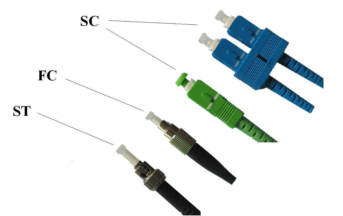
Fig 1: Various types of Optical connectors

Fig 1: Various types of Optical connectors

Starting in the mid 1990’s, several building wiring standards, usually based on the American EIA/TIA 568 series (eg, Australian/New Zealand AS/NZS 3080), were released that specified the SC type connector for most applications within premises wiring systems.  Unfortunately, many people have interpreted this to mean that ALL optical connectors must therefore be SC.  This issue comes up quite regularly at OSD when we are asked to supply our equipment with SC connectors in the belief on the part of the customer (or his consultant) that the SC is mandated throughout his communication system or network.  As a matter of interest, TIA 568 does actually consider other connector types (e.g. the Small Form Factor (SFF) connector) to be acceptable where their higher density is needed, but this innate flexibility is often ignored by potential users.

In reality, standards such as TIA568 or AS3080 are not intended to specify the optical connectors on the communications equipment using the premises wiring scheme because they are focussed purely on the premises cabling issues.  And, of course, because specifying the connectors on equipment is totally impractical.  Many products do in fact offer the SC connector as one of their connector options (in some cases the only option) but there are many which do not.  This is due to a variety of reasons such as historical ( the product was originally designed before the SC became popular and it just isn’t economic to redesign), practical (some products are simply too small to be able to accommodate the SC or active SC based transmitter or receiver components are not available) or performance (many telecommunications manufacturers and operators would prefer to standardize on other connectors such as the DIN connector because of perceived advantages in terms of optical loss, return loss and ruggedness).  As an example of these issues, OSD manufactures some industrial products using the FC connector because it is considered to have better performance under extreme vibration conditions.

TIA-568-C.3, released in June 2008, recognises the dynamism of the fiber optic industry by specifying performance as the key determinant in the selection of connector types for use within the premises cabling system and still leaves the connector types used on electronic equipment up to the manufacturers.  Thus it refers to the need for connectors to meet the corresponding TIA Fiber Optic Connector Intermateability Standard (FOCIS).  These are detailed in the series of standards under TIA-604.

So what does all this mean for users of fiber networking equipment?  Basically, it means that you do have quite a bit of flexibility so that within fairly broad guidelines you can use the connectors best suited to your application.  Overall, we at OSD would recommend that the SC connector, being a reliable, well established high performance component, should be used as your default connector for cable termination enclosures, cross-connects and the like in commercial premises.  It can also be used in many industrial sites with some caution but at sites where there is significant dust, pollution, vibration or extreme temperatures there may be better choices.

However, in any case we also strongly suggest that you leave the design of the equipment to the manufacturer and use mating patchcords to connect from the building wiring closets fitted out with SC connectors to that equipment.

How Far Can You Go?

This is a question we are often asked by customers in relation to almost all of our products.  The answer, of course, is: “It depends”.
It depends on several things:

  • The individual product
  • How the product is configured (eg type and power of the laser, type of photodiode)
  • The type of fiber: multimode or singlemode
  • The quality of the fiber.

The simplest constraint on transmission distance is the loss budget: in the most basic case you simply divide the difference between transmit power and receiver sensitivity by the fiber loss per kilometer at the system’s operating wavelength and that is your answer.  For example, an OSD139 RS232 modem couples at least -25dBm at a wavelength of 850nm into 62.5/125um multimode fiber and the distant OSD139’s receiver will have a minimum sensitivity of -47dBm.  The loss budget is the difference, ie 22dB, which when divided by the worst case fiber loss of 3.5dB/km suggests the system will operate over at least 6.3km.  The singlemode version of the OSD139 also has a loss budget of 22dB but at a wavelength of 1310nm (where the fiber loss is less than 0.4dB/km) so it can operate over at least 50km.  Any sensible design will also take into account any connectors and splices along the way (eg at patchpanels) as well as allow for a link margin that is chosen partly because of intrinsic mechanisms such as degradation of optical output with time and temperature and partly because of site conditions.  Typically, such margins can vary between 3dB and 6dB.  In some extreme situations OSD has even allowed for as much as 10dB when it was feared that the optical cable would get damaged fairly regularly so that the splices needed for the repairs would slowly eat away at the margin.

However, transmission limitations caused by fiber bandwidth issues are often a far more critical issue and generally do not seem to be well understood by many users.  It is useful to review these issues separately for multimode and singlemode fibers as the mechanisms are quite different.

Before we start, it is probably worthwhile to briefly review the term “bandwidth”.

The bandwidth of a communications medium (like fiber or copper cable) is the range of frequencies that can be transmitted through it.  A typical telephone call requires about 3000 Hertz (3kHz) in order to transmit the most important freqencies in human speech.  If you want high quality you will extend this to cover all frequencies human hearing can handle, ie to about 20kHz.  And if this is to be extended so that television images can be included as well then this is increased to about 5 or 6MHz.  Older fiber optic systems transmit audio and video in a simple “Amplitude Modulation” (AM) format which only needs this base bandwidth.
However, nowadays almost all modern communications are digital in nature and this can dramatically increase the bandwidth requirements.  For example, it is quite common to digitally encode and transmit video signals at speeds of up to 400Mbps for standard definition television (a lot more for High Definition).  Such a data rate requires a transmission channel that has a bandwidth of at least 250MHz.
And, despite what many people think and as indicated above, optical fibers do actually have bandwidth limitations.

Multimode Fiber Bandwidth

Multimode fibers are so-named because they allow many ray paths of light to travel through their core region, something like several hundred distinct paths (or “modes”) in a typical 62.5/125 multimode fiber and the time light takes to travel along all these ray paths will vary slightly with each path (see figure 1 below).  These slight propagation delay variations are equivalent to a reduction in the fiber’s transmission bandwidth.  A good multimode fiber optimised for operation at 1300nm might have a dispersion of 0.3 to 0.8ns over 1km which very roughly corresponds to an achievable system bandwidth of from 1GHz to 400MHz.  While 400MHz can theoretically support as many as 80 AM video channels it would only be enough for just a few uncompressed digital channels.  Unfortunately, the fiber dispersion increases with increasing distance.  A worst case assumption would be that it increases linearly with distance but in practice it increases roughly to the 0.75 power of distance or, put another way, the bandwidth reduces to the 0.75 power of distance.  So our example multimode fiber might be 400MHz over 1km but would reduce to about 120MHz over 5km: not all that useful for many high data rate applications such as uncompressed digital video.

Figure 1: Mode ray paths in multimode fiber

Figure 1: Mode ray paths in multimode fiber

There are many other related issues that affect the usable capacity of a multimode fiber but this simple example does illustrate a stark reality of modern uncompressed digital systems: they are really quite limited when it comes to multimode fiber.

Of course, when a video codec is used to encode the video using a compression standard such as MPEG4, MJPEG2000, H.264 or several other techniques the transmission bandwidth is reduced dramatically to anything from less than 100kbps (slow frame rates and/or poor quality) to greater than 10Mbps (standard frame rates and high quality image) so such systems which typically use an Ethernet network to transport them between source and user(s) are really only affected if the Ethernet network itself suffers from some sort of congestion.

Singlemode Fiber Bandwidth

All fiber types are affected by bandwidth limitations caused by the interaction between the transmitting device (Light Emitting Diode (LED) or one of two main types of laser) and the material used in the fiber. The speed of light within a material depends on both the refractive index and the actual wavelength being transmitted.  Optical devices actually transmit a narrow range of wavelengths and it is this range of wavelengths (or spectral width) which results in this “chromatic dispersion” (see figure 2 below) and this ranges from <3ps/nm of spectral width/km at 1310nm to 17ps/nm of spectral width/km at 1550nm.  While this can be a major problem in higher speed multimode systems it is the main bandwidth limitation in singlemode systems.  (There is also a minor limitation called waveguide dispersion which can actually cancel chromatic dispersion at just one specific wavelength).

If the laser used to transmit the signal was a perfect single frequency then it would have an extremely high bandwidth distance product allowing transmission of data rates in excess of 10Gbps over hundreds of kilometers at any wavelength.  However, as noted above, commercially available devices are not so perfect and actually transmit energy over a narrow range of wavelengths.  For example, LEDs mostly used in multimode systems can have from 20nm to 100nm, the low cost lasers typically used in short distance systems are usually the Fabry Perot (FP) type and have a lasing spectrum of 2 to 5nm whereas the higher performance Distributed Feedback (DFB) types used in telecommunications and other long distance systems will normally have a spectrum from 0.02 to 0.1nm.  Guess which is the most expensive!

Figure 2: Chromatic Dispersion

Figure 2: Chromatic Dispersion

To illustrate what is achievable with a typical high quality digital product let’s look at the OSD8600 4-channel video multiplexer.  This unit transmits at an optical data rate of 900Mbps which means it needs around 500MHz system bandwidth.

Multimode systems using standard FDDI grade fiber will support this to at least 1km.  In reality, almost all modern fibers are much better than this and operation over 2km is usually achievable.  However, we at OSD are very conservative and would suggest that you not use the product over much more than 1km.

Now look at the same product on singlemode fiber.

If operating with an FP laser at 1310nm the chromatic dispersion induced bandwidth may be as low as 30GHz.km so this will limit operation to 60km.  At 1310nm this corresponds to 20 to 24dB of optical loss which is greater than the 15dB available with the OSD8600’s usual optical devices: typically these are good for a loss budget of 15db which corresponds to around 30 to 40km assuming a loss of 0.4dB/km at 1310nm, less if a link margin is included.

On the other hand, at 1550nm the fiber bandwidth with an FP laser will be closer to 4GHz.km which would allow distances of less than 8km.  So to take advantage of fiber’s low loss at 1550nm we need to use a DFB laser.  This leads to a bandwidth of  about 170GHz.km so we are now fiber bandwidth limited to possibly 300km.  Given that our best combination of laser and receiving devices would be good for about 37dB at 1550nm we can see that our maximum achievable distance is closer to 180km, assuming a loss of 0.2dB/km at 1550nm.

While none of this is rocket science it is commonsense for anyone looking at doing anything out of the ordinary to be aware of the fundamental limitations of fibers and of some of the techniques used by companies like OSD to fully exploit the technology.

Please don’t hesitate to contact OSD’s system engineers for any further information or for any assistance in estimating…………. how far can you go.