


Abstract
CCTV has traditionally used analog transmission to move pictures from cameras to displays. Currently, this technology is slowly succumbing to IP oriented technology although analog-like SDI uncompressed digital systems are gaining traction in some specialised applications. In all cases, copper based technology has limitations in terms of distance and interference immunity so that fiber is often the preferred, sometimes the only, way of distributing signals around CCTV networks. In this technical corner will discuss fiber optics in CCTV the best ways to make effective use of the technologies now available.
Introduction
Over the past 10 to 15 years CCTV has become ubiquitous and while many applications are related to security almost as many are related to operational and safety matters. For example, road operators have been using CCTV for well over 30 years for monitoring traffic flows in many cities and large towns with fiber first being used in this application well over 20 years ago.
Until fairly recently, CCTV used technical standards derived from broadcast television and characterising quality performance of systems likewise derived from the techniques and equipment typically used in the broadcast industry. The advent of IP based CCTV and newer technologies related to High Definition (HD) TV have considerably widened the scope of surveillance systems. Consequently, we now see a mix of both analog based and network based technologies, the former using coaxial cable and the latter using Unshielded Twisted Pair (UTP) cable, typically so-called Cat-5 cable.
While coaxial cable is very easy and convenient to use, it does have limitations:
- Link distances are typically restricted hundreds of meters unless in-line amplifiers are used
- Susceptibility to interference from electrical machinery, lightning and other electronic equipment
- Ground loops can cause major problems
- Obviously, there are ways of reducing these issues but eventually coax runs out of puff.
Often it can be inconvenient to install coax cable and if UTP is available then there is a great incentive to use it. However, similar issues arise when trying to use UTP cables to transmit analog video signals. Typically, passive or active Balanced-to-Unbalanced converters (Baluns) are used and these can provide reasonable transmission over a few hundred meters (even more with active cable equalisation). The Ethernet systems typically deployed in local area networks are often used to transfer IP based video signals but as with coax and balun based analog systems, these also have severe distance limitations and are susceptible to EMC issues.
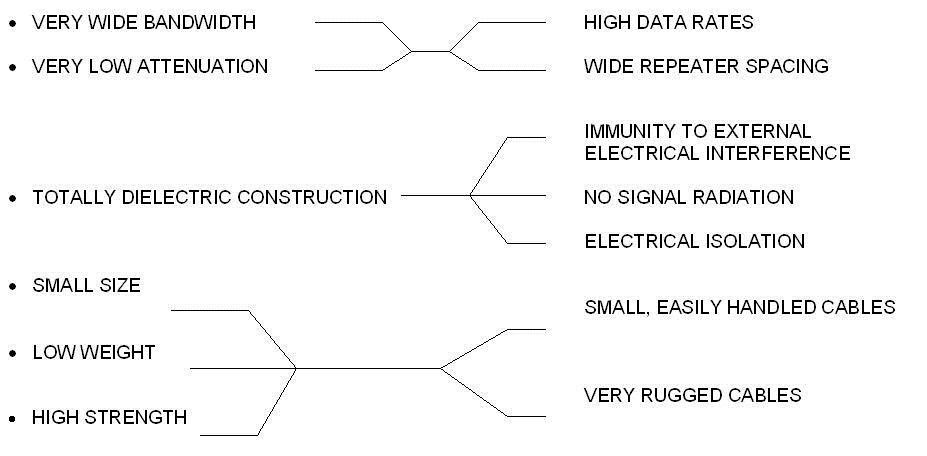
Which is where fiber optic technology comes into play: where distance or EMC are a problem fiber is a very straightforward technical fix for many situations. Fiber has some excellent technical features:
Fiber Types
We have spent some time in past issues discussing optical fiber, how it works and the technical parameters of singlemode and multimode fiber so we will not go into all of it here. Please see Technote – ‘Fiber types and using them effectively’ and ‘Singlemode vs Multimode’.
Applying Fiber to CCTV
Over the past 15 years CCTV technology has slowly moved from the original broadcast industry analog technology based on coaxial cable to systems in which the video is digitized, compressed and transmitted via local network technologies, typically using Ethernet running Internet Protocol (IP) over UTP cabling. The digitization and compression may occur within the camera or externally in a local video encoder or perhaps back at the control room within a DVR. The quality of IP cameras and the schemes used to compress and transmit the video signals has improved dramatically over the past few years but it is still the case that almost all the highest quality cameras are analog output types. Due to this and the (for now) lower cost of analog cameras as compared to equivalent quality IP cameras, analog systems are still popular for general use while in specific applications such as highway or tunnel traffic monitoring many systems engineers are still specifying analog units for reasons such as video quality, zero latency and ease of control. A further “back to the future” wrinkle on this progression has been the application of the broadcast industry’s SDI (Serial Digital Interface) technology to high end CCTV systems over the past few years.
Analog Systems
Transmitting analog television signals through fiber has progressed through three phases:
- AM (Amplitude Modulation ) systems
- FM (Frequency Modulation) systems
- Digital systems
The first commercially available fiber CCTV systems were AM. They offer good video performance over several km but the signal does degrade with distance. This technology is still widely used for simple video only links on multimode fiber where it very economically provides more than adequate performance.
FM systems came next and overall technical specs are usually better than AM, they tend to have more constant performance with distance and they operate happily over both MM and SM fibers.
Finally, uncompressed digital systems can have very high performance which does not change with distance (until it falls off a cliff) and is probably best with SM but is also commonly used with MM.
Pricing does increase a little going from AM to FM to digital but not excessively. For example, Figure 1 shows two small transmitter modules that plug onto the camera: the AM unit retails for less than $100 whereas the digital equivalent is about 30 to 50% more expensive. Of course, the digital’s performance is vastly superior!
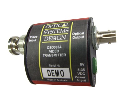
Figure 1: Small AM and Digital Video Only Transmitter Modules (OSD365A)
A key issue in this improvement in technology from AM to FM to digital is that the bandwidth requirements do increase fairly dramatically . An AM system needs just the video bandwidth, ie 5 to 10MHz which means that with standard 500MHz.km MM fiber operation over about 100km might be possible if it wasn’t for the fiber attenuation.
A basic FM system will require 30 to 50MHz so can operate over around 10km of MM.
On the other hand, digital systems operate at bit rates somewhere between 100Mbps (very basic 8-bit systems) to over 350Mbps (high end) which means optical bandwidths of 90 to 300MHz are needed. Therefore, it is difficult to be able to guarantee reliable operation over much more than a few km on MM fiber for most such products. Consequently, digital modems and multiplexers are best suited to SM fiber. For more on fiber bandwidth issues see Tech Corner “How far can you go?”.
IP Systems
IP CCTV systems have started to dominate many areas of video surveillance for many good reasons such as the flexibility in placement of cameras and the theoretical ease of integrating the surveillance of a building, campus, etc into the existing IT local area network. Clearly, there are differing viewpoints about the practicality and/or advisability of incorporating CCTV into an existing IT network but it can be done successfully provided due allowance is made for both average and peak transmission requirements of the CCTV. Typically, the video image quality seen at the control room rarely approaches that of well designed analog systems because:
- Basic camera optics, sensor and analog processing are sometimes inadequate
- Video encoder (within camera or external) and software decoder are not of high quality
- The transmission rate has been choked in order to allow the network to breathe a little, which typically results in noise, blockiness, reduced frame rates and excessive latency.
All these issues are being addressed by system vendors so that excellent quality is now possible, provided the network can handle the increased data rates required for high quality equipment and software. For Standard Definition (SD) video this could be an average of 0.3 to 1.0Mbps with peaks of 10Mbps or even greater. However, megapixel cameras can increase this dramatically with average rates of 5 to 10Mbps for some types. Most networks will operate at 100Mbps out of the camera or encoder and feed either directly to a switch located in a central equipment room or to that switch via a backbone network. This backbone will sometimes be 100Mbps but more usually it will be Gigabit Ethernet such as the redundant ring network shown in Figure 2. Clearly the number of megapixel cameras that can be supported on any network will be a lot less than is possible with standard cameras. Alternatively, larger networks may need to move towards 10Gbps backbone technology.
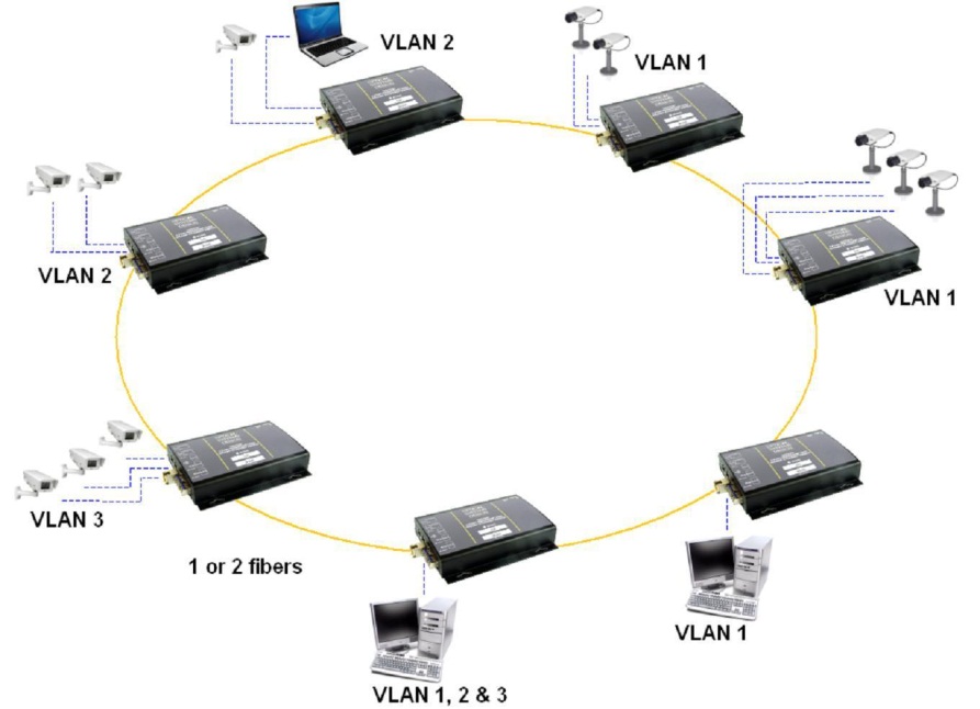
Figure 2 Typical Redundant Ring Gigabit Backbone Network
Unfortunately, most backbone networks use MM fiber which really isn’t all that good. As has already been noted, the fiber used has changed from the original 50/125 design to 62.5/125 and back to 50/125 over the past 20 years or so:
- Most legacy fiber has been supplied to meet the old FDDI specification (Fiber Distributed Data Interface, an old standard for token ring based backbone networks) and is usually known as OM1. This is 62.5/125um and has serious limitations in terms of fiber bandwidth, ie 160MHz.km @ 850nm and 500MHz.km @ 1300nm. This is fine if you are running Fast Ethernet over a few kilometers but starts looking a bit shaky once you have Gigabit speeds and really problematical once we are talking 10Gbps.
- OM2, OM3 and now OM4 50/125um fibers have been developed to improve the performance at 850nm when using VCSEL light sources and these enable 1G and 10G operation over hundreds to several hundred meters. Still somewhat limiting when networks move outside buildings.
Operation at 1300nm over multimode fiber is sometimes needed, eg when using SM oriented equipment and some care is needed to ensure reliable operation. We have covered some of the issues in Tech corner that can arise in such situations and the consequent need for Mode Conditioning Patchcords (MCP).
Of course the other solution to the limitations of MM fibers is just to completely replace them with singlemode fiber and singlemode equipment. This enables you to move seamlessly from generation to generation of technology without touching your network backbone cabling. In fact, to be absolutely sure that your infrastructure does not need any upgrading, also install APC (Angled Physical Contact) connectors on all your new SM fiber with all the benefits APC technology gives you. In Technote, “Selection of Optical connectors” goes into some detail on the different connector types and their features.
SDI Systems
Given the enormous emphasis placed on IP systems by vendors, consultants and end users over the past several years it would be reasonable to assume that this is the ultimate technology for CCTV. Both the original analog technology and then compressed digital technology on which IP systems are based came out of the broadcast industry. Now another broadcast originated system is being applied to CCTV: Serial Digital Interface (SDI). This is a series of standards that started with uncompressed Standard Definition (SD) video running at 270Mbps over coaxial cable and which is also now available for High Definition (HD) at 1485Mbps and at 2970Mbps. It is very likely that the next SDI standard will operate at around 10Gbps.
The great thing about SDI is that it is about as pure a digital video signal as it is possible to get so that with good cameras, lenses and transmission technology there are very few impairments in the pictures. Thus, for a minority of higher end CCTV applications it is a very useful technique. An example might be where centralised video analytics are being used in high risk sites such as airports where there is little margin for the distortion and noise that might accompany even high quality IP systems.
In some ways the SDI solution looks like an analog solution: camera, 75Ω coaxial cable and BNC connectors and can, theoretically, use the same copper cabling infrastructure already in place for conventional analog CCTV. There are now many surveillance oriented cameras that have a native HD-SDI (1.485Gbps) or 3G-SDI (2.97Gbps) interface. Unfortunately, the distance these systems can transmit over the coaxial cable is somewhat limited: from 140 or so meters using HD-SDI, to as little as 70 metres using 3G-SDI – somewhat similar to the old analog technology. In fact, this compatibility with existing coaxial cable infrastructure is often touted as the key motivation for the move to HD-SDI technology: just replace your cameras and a few components at the control center and “Bingo” – HD zero latency images without the hassle of an IP network.
Note also that these numbers assume good quality coaxial cable: attempting to make SDI work with rubbish cable is contra-indicated.
Such transmission distances are too short to be practical in many CCTV networks, so fibre optic systems are often essential and a growing range of SDI products is available for the CCTV industry.
It is certainly best to use SM fiber with these systems but operation with MM fiber is often practical, although it may be necessary to use MCPs.
Cables and Connectors
There are many different cable types which tend to be divided into those most suitable for either indoor and outdoor deployment. Most cables used in conventional commercial or industrial outdoor sites do not move once installed so designs such as the loose tube are ideal. Figure 3 illustrates the cross section of a 6-tube design. It has great flexibility in that the individual tubes can each carry from 1 to 12 individual fibers or, in some designs, from 1 to 6 or more 12-fiber ribbons. The cable’s central strength member will usually be dielectric (for example, fiber reinforced plastic, FRP) but can also be metallic. The FRP core is usually quite stiff so bending radii of 500mm or so are quite common which means that this design is not so suitable for in building use where a fair degree of flexibiliity is needed. Some sort of filling is often used inside the tubes to prevent water migration up the cable. Such fillings can be gels or dry powder that expands in contact with water.
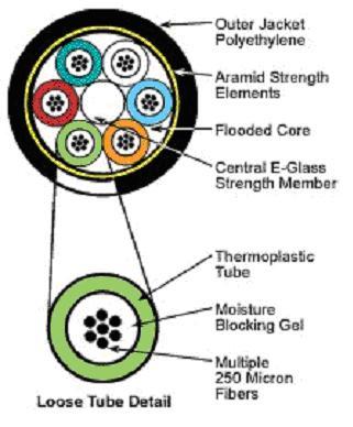
Figure 3 Loose tube outdoor cable cross section
Distribution (or riser) cables used within buildings need to be flexible, strong and must often meet stringent requirements such as low smoke, zero halogen flame and flame retardancy. The most common design is the tight buffer illustrated in Figure 4.
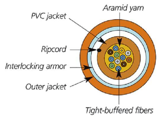
Figure 4 Tight buffer distribution cable
The fibers in tight buffer designs typically have a secondary plastic coating (hytrel or nylon) that takes the diameter up from the usual 0.25mm to 0.9mm. The fibers are then just bundled together and surrounded by Kevlar for strength and then an outer jacket such as PVC or polyurethane is added.
Single tube variants of the loose tube design are also used in buildings as distribution cables. Such cables have up to 24 fibers in the central tube that will be surrounded by Kevlar and then a plastic jacket and are flexible enough for indoor use.
Usually, cables are terminated in Fiber Optic Breakout Trays (FOBOTs) with the terminated trunk fiber appearing via a through adapter (SC in most Australian installations). Connection to the equipment is via a patchcord which will be SC at the FOBOT end and commonly ST, SC or LC at the equipment end. This was earlier discussed in detail in Tech Corner – “The selection of optical connectors”.
Testing
When a cable is installed and terminated the installer will normally test his work. This should include loss measurements using a power source and an optical power meter and very often will include bothway OTDR (Optical Time Domain Reflectometer) measurements which give a very good picture of the loss of all components of the cabling: cable(s), connectors and splices. Such “certification” is highly recommended in all but the most straightforward installations as it not only establishes the real loss performance on Day One but gives you a reference for any future issues that might arise. Do note that all such OTDR measurements should be carried out at both 850 and 1300nm for MM and at 1300 and 1550nm for SM. Good results on a SM link at 1300nm do not guarantee good results at 1550nm: small imperfections in fiber handling that barely affect SM fiber at 1300nm can cause major problems at 1550nm.
After the link has been installed and the fiber installation specialist has been long gone what do you do if you have a problem with the system? The first and most obvious action is to check if the fibers are still working correctly. Many transmission equipments will have some sort of indicator for the received optical signal: it may be a simple “OK/NOT OK” LED on the front panel or it may be embedded in the GUI software and actually show the received optical power level. Or, you may have nothing obvious to look at.
We would strongly recommend to anyone with more than a few fiber links in their plant or network or to anyone involved in installing fiber systems that they consider buying a simple low cost (less than $800) optical power meter: it is a great investment which can save you a lot of wasted time. With an optical power meter you can measure the output of transmitters, check receiver sensitivity and overload problems and measure the optical loss of cables, connectors and splices. A power meter is all that’s needed for 90% of organisations. A visual fault indicator which injects intense red light into the fiber is also handy for identifying breaks or fractures in fibers up to hundreds of meters away. Of course, if your operation cannot tolerate any downtime at all and/or you are in a remote area then an OTDR and fusion splicer might also be advisable.
Summary
Fiber is a well established technology that can offer enormous benefits to end users in enabling interference free transmission over almost any distance of high quality video, whether it be in analog, IP or SDI formats. The fiber type used will often have been already decided due to factors outside the user’s control but if not it is recommended that singlemode be looked at very seriously. Using APC style connectors for such SM infrastructure is also recommended. Factors such as the type of cable to be used will be determined by site conditions, eg typically loose tube types for the longer outdoor runs and tight buffer (aka distribution) within buildings. It is always recommended to use FOBOTs to interface between the cabling and the equipment. Various standards either recommend or mandate the use of the SC type connector for this building cabling but please note that the standards do not specify which connectors should be used on the transmission equipment: this is up to the manufacturer. Consequently, much use is made of patchcords with an SC on the FOBOT end and an ST or LC or whatever on the equipment end.
It is recommended that OTDR based testing of new installations other than the most simple be carried out and a record kept of these results. It is also suggested that an optical power meter be readily available for quick checks in case of any issues.