


At OSD we have been saying for years that singlemode fiber is far better technically than multimode and that the cost premium once seen for SM equipment is slowly starting to disappear. In fact, most of OSD’s new products over the past two or three years are much the same price whether they are MM or SM. In some situations, MM is actually more expensive. However, the fact is that there is an awful lot of MM fiber out in the field and people want to continue to use it for as long as possible, even though the technologies they may be employing are constantly being updated. The classic example of this, of course, is Ethernet which has progressed from its humble 10Mbps origins to “Fast” Ethernet at 100Mbps to Gigabit Ethernet and now we are seeing growing deployment of 10G Ethernet. As always, the newest technology tends to be used in the backbone portion of networks but eventually flows down to the desk.
One problem with MM fiber in all this is that it really isn’t all that good. Its limitations come in two flavours:
- Most of it has been supplied to meet the old FDDI specification (Fiber Distributed Data Interface, an old standard for ring based backbone networks) and this has serious limitations in terms of fiber bandwidth, ie 160MHz.km @ 850nm and 500MHz.km @ 1300nm. This is fine if you are running Fast Ethernet over a few kilometers but starts looking a bit shaky once you have Gigabit speeds and really problematical once we are talking 10Gbps.
- Most fibers made to this spec have been designed to operate with LED (Light Emitting Diode) light sources which tend to “fill” most of the core area of the fiber. Consequently, a serious production flaw in most FDDI fibers does not cause many issues with such source. This flaw is the center dip in refractive index profile of the core region. You may recall that the profile of a Graded Index MM fiber is a peak on the axis of the fiber and drops down towards the cladding and should ideally follow a nearly parabolic curve over this area. Unfortunately, several of the most popular fiber manufacturing techniques have a tendency to leave a dip or other imperfection in the refractive index along the axis. This dip may be just a slight flattening or may be quite extreme, possibly coming as low as the index at the core/cladding interface as indicated in Figure 1 below.
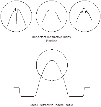
Figure 1. Typical refractive index profile of ideal GIMM fibre and some examples of fiber central core profile distortions (dip / flat top / peak).
As previously noted, if the light source fills up all of the core area AND it is fairly incoherent light (ie an LED) this isn’t such an issue but it can lead to some very troublesome effects if the source is a laser (which is pretty coherent) AND it is well collimated light travelling down the core’s axis. In such a case the effective bandwidth can be a lot less than the fiber’s specification. The effect on transmission is that different propagating modes see different path lengths which will vary with temperature and laser drive levels in a fairly unpredictable manner. Figure 2 illustrates the effect on a single pulse of light (a data bit). These distortions will vary from pulse to pulse so that severe distortion (Differential Delay Distortion or DMD) will result which in turn leads to so-called intersymbol interference that causes bit errors in the system.
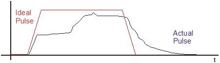
Figure 2: Example of a distorted pulse due to DMD
One solution to Problem #1 above propounded by anyone with a vested interest in selling optical cables, connectors and equipment is that you change your old FDDI multimode fiber to a new multimode fiber that has a lot more bandwidth. Bizarrely enough, this is a change from the old 62.5/125 FDDI fiber optimised for 1300nm operating wavelength to the “new” 50/125 fiber optimised for 850nm, the operating wavelength of the vast majority of the laser device typically used in these systems (VCSEL, ie Vertical Cavity Surface Emitting Laser). Typically, such systems will not experience much of Problem #2 because the VCSEl illuminates a fairly large part of the fiber core area so that there are not too many issues with light travelling along the core axis.
It is rather interesting that the original fiber widely used for multimode applications was also a 50/125 design optimised for 850nm. Of course, the modern version is lower loss and does have higher bandwidth (2000MHz.km @ 850nm) but given the fact that VCSELs are only marginally lower cost devices than standard 1310nm lasers the economics of this is very questionable since MM fiber is usually a lot more expensive than SM fiber.
The other solution propounded by a few system vendors such as OSD is to totally move over to singlemode fiber and singlemode equipment. This enables you to move seamlessly from generation to generation of technology without touching your network backbone cabling. In fact, to be absolutely sure that your infrastructure does not need any upgrading, also install APC (Angled Physical Contact) connectors on all your new SM fiber with all the benefits APC technology gives you as described in Tech Note 201001. Some of OSD’s customers have been doing this for years.
However, unless the very best and latest MM fiber technology is installed, there may still be an issue with Problem #2. If the light source is 850nm it is normal to employ a VCSEL which injects into the fiber a broad range of ray paths such that those most subject to DMD effects are a very small portion of the total optical power being transmitted through the fiber. In the case of 1310nm systems where the light source is typically an FP laser with well collimated light the solution to this is to try to avoid sending light along the axis of the fiber’s core and one way to do this is by using a Mode Conditioning Patchcord (MCP). The MCP (see Figure 3) usually consists of a singlemode fiber spliced to a multimode fiber with their axes offset by about 19um (62.5/125 fiber) or 12um (50/125 fiber) so that 1310nm light from the 1310nm laser transmitter (typically the 1000Base-LX of Gigabit Ethernet) is connected to the SM fiber and then coupled into higher order modes of the MM fiber. This ensures that little energy travels along the “bad” part of the MM fiber, i.e. the core axis, thus avoiding the DMD illustrated in Figure 2.
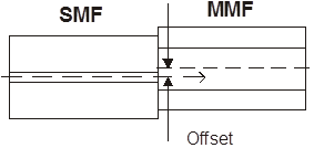
Figure 3: Illustrating the offset between SMOF & MMOF axes
MCPs are available from many vendors so it is important to know where and when they should be used. See “Mode Conditioning Patchcords” examines these issues.