


Anyone who has read a few of these Tech Corners will have noticed a certain cynicism with respect to the marketing of multimode fibers and our constant exhortation : don’t do it! By almost any measure and in almost all situations singlemode is the better option. Rather than explore the world of network equipment and cable marketing (as entertaining as this might be) we will this month continue to stick to our technical knitting and explain some of the more arcane issues with multimode fiber. Of course, singlemode can also have its moments and in Tech Note “Angled Physical Contact (APC) connectors” we looked at the problems caused by reflection noise which applies to both singlemode and multimode fibers. Fortunately, such noise is more easily controlled in singlemode systems than in multimode systems.
We have already discussed some of the vagaries of multimode fiber bandwidth which is roughly inversely proportional to distance 0.75 . This exponent can, in fact, vary from 0.5 to 1.0 (best case to worst case) and is very dependent on the specific fibers and how light is coupled into them so calculating the bandwidth budget for a multimode system is not very precise.
Another issue with multimode fiber is actually much more critical: in fact it can be a complete show stopper. An example: In the mid 1970’s a major field trial of a 140Mbps PDH system was being commissioned by British Telecom and it was found that the system was very unreliable: it would operate perfectly for a short while then the error rate would go through the roof and the system would crash. Others had seen some similar effects but nothing quite as spectacular as this system. The effect was traced to two related phenomena:
- Modal Noise
- Modal Distortion
The major problem in this particular case was modal noise. Our primary optical emitters in fiber optic systems are Light Emitting Diodes (LEDs) and lasers (either Fabry Perot (FP) or Distributed Feedback (DFB) types) with so-called super luminescent diodes somewhere between the two and only used in specialty applications. A key difference between LEDs and the two main laser types is the spectrum as shown in Figure 1 below.
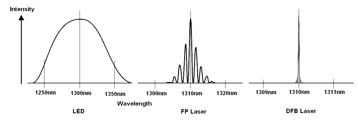
Figure 1. TYPICAL SPECTRA OF LED, FP LASER AND DFB LASER
The LED has a very broad spectrum of around 30 to 40nm at 850nm increasing to 80 to 100nm at about 1300nm. The light is incoherent and of completely random phases and frequencies within this envelope. The FP laser is far more coherent with (usually) several discrete spectral peaks at different wavelengths occupying 2 to 5nm total width. The DFB is even more pure with typically just one peak with a small number of adjacent peaks that are at least 20dB down (ie they are 1/100 of the amplitude of the main peak).
The emitters used in the BT field trial were very high quality FP types (with just one main central wavelength) and this is where things went off the rails. To simplify the explanation let us assume that we are using a DFB laser to transmit through a MM fiber as illustrated in Figure 2.
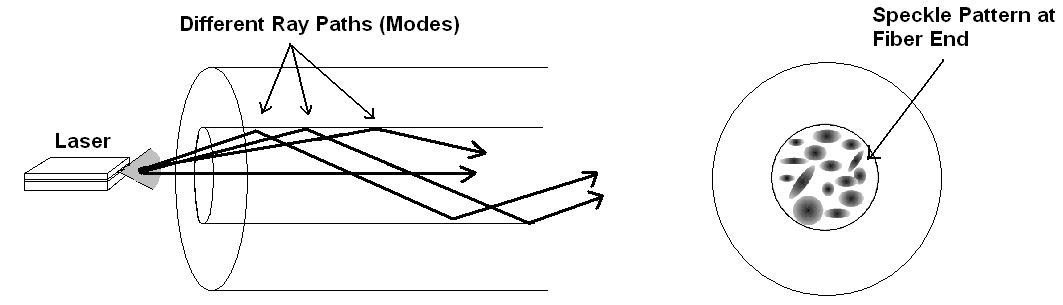
FIGURE 2. COUPLING A DFB LASER TO A MULTIMODE FIBER
So far so good: the left side of the sketch shows a few of the several hundred ray paths possible within the core of the fiber while the right side shows what you would see at the end of the fiber tens or hundreds of meters away from the laser. Now, remember what these rays actually are: propagating electromagnetic waves which can be any one of many different modes. If we look at the end of the fiber we see a pattern of light and dark spots (so-called speckle pattern) which are due to the constructive and destructive interference of the light at the end of the fiber. An interesting aspect of this phenomena is that the pattern is rarely ever static: the spots are in constant motion. This is due to a number of reasons:
- The distribution of light energy coming out of the laser varies a little with time, temperature and random circuit fluctuations.
- This distribution’s changes are also dependent to some extent on the current passing throught the laser (which in a digital system varies from just above the lasing threshold of 5 to 25mA to possibly 50mA above that threshold).
- Mechanical changes to the fiber (eg bending, torsional or compressive forces) will affect the light propagation.
Now, what happens if the fiber is terminated in a connector which has a little bit of radial offset as shown in Figure 3 below? The speckle pattern out of the fiber is mostly coupled to the receiving fiber with very little energy loss BUT because we actually have dark and bright spots moving around over the receiving fiber core there is a variation in received optical power that is seen by the system as noise.
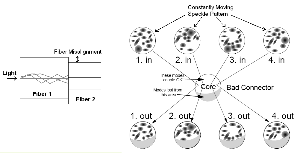
FIGURE 3: MODAL NOISE DUE TO CONNECTOR OFFSET
The question is: does this really matter with low loss connectors? In the case of the BT trial system the connectors had losses of up to 2dB so the answer was emphatically Yes as the effective noise was sufficient to render the system unusable.
These days, it would be very unusual to see connector losses as high as 2dB so this issue should not normally be of major significance with digital systems but the phenomenon can be a major issue with analog systems which normally require a much higher Signal to Noise Ratio (SNR). As previously mentioned, another serious show stopper, at least with analog systems, is modal distortion. This comes about because the transmitted modes out of the laser are not stable with time or with drive current through the device. As the current increases from below threshold to the device’s maximum the dominant modes will change. This may not be an obvious problem if the laser is connected directly to the receiver but once modes selective mechanisms like imperfect connectors are part of the link we see some very nasty distortion effects. Similar effects can also occur due to reflections from the fiber back into the laser cavity.
Again, with fully digital systems this may not be too serious but in analog systems it is quite critical. This is one of the reasons very few manufacturers would encourage transmission of CATV signals over multimode fiber.
Oh, and what did they do about that field trial mentioned at the beginning of this Note? The equipment designers analysed the problem, figured out what was happening and changed the system from Non Return to Zero (NRZ) operation to Return to Zero (RZ) then operated the lasers from below threshold. This had the effect of broadening the laser spectrum so that the problem was eliminated and the trial ended up as a great success. Brilliant engineering!
Don’t hesitate to contact your OSD Systems Engineer for any further information on this subject.