Before we go in to details of tests that should be performed on a L2 switch, let us look at its internal workings. Figure 1 below shows the data paths inside a multiport Gigabit layer 2 switch with major functional blocks that process the frames as they traverse the device.
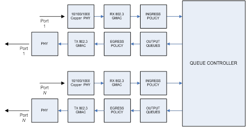
Fig 1: Switch Data Flow Diagram
PHY – Physical interface to receive and transmit frame to and from a port’s Gigabit MAC.
GMAC – Gigabit Media Access Controller responsible for frame formatting, frame stripping, FCS (Frame Check Sequence), CSMA/CD handling and collision handling.
Ingress Policy – Used to modify the normal flow of frames through the switch. Ingress policies examine an incoming frame for Quality of Service (QoS) priority information for the Queue Controller. These ingress policies determine the states of the switch management ports and implement features like Port Based VLANs or 802.1Q VLANs (tag processing).
Queue Controller – The brain of the switch which controls the switching architecture.
Output Queues – The output queues transmit the received packets in the order received for any given priority. These queues empty at different rates depending on port speeds or network congestion.
Egress Policy – Egress policy examines outgoing frames and modifies them (Tagging/Un-tagging frames based on 802.1Q or Port based VLANs) as they exit the switch.
Now that we have briefly described the main logic blocks of a switch, let’s discuss some of the testing scenarios.
RFC 2889 Tests
The following tests are as per RFC 2889 for different port traffic patterns, traffic loads and frame sizes.
Forwarding Rate, Throughput and Frame Loss
RFC2889 is thorough in its approach to testing layer 2 switches. It takes in to account different traffic scenarios such a fully meshed traffic pattern, partially meshed and non-meshed pattern to test forwarding rate (max frames per second), throughput (maximum load with no frame loss), frame loss and flood count which is the number of frames output from a switch port that are not specifically addressed (destination MAC) to a device connected to that port.
A brief description of the traffic patterns in as follows,
Fully Meshed: Many to Many – This test determines if the L2 switch can handle a full mesh of traffic (from all-ports to all-ports) at various traffic loads (Fig 1). Fully meshed traffic stresses the switch fabric, fully exercises the forwarding tables and reveals weaknesses in resource allocation mechanisms.
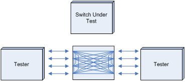
Fig 2. Fully Meshed Traffic Pattern
Partially Meshed: One to Many/Many to one – Traffic is sent from one to many ports or many to one port in this pattern. This type of port traffic pattern stresses the three main logic sections of a switch: the ingress data path interface; the switch fabric that connects the ingress ports to egress ports; and, the egress data path interface. Caution should be used in the many-to-one test to avoid oversubscribing the “one” port.
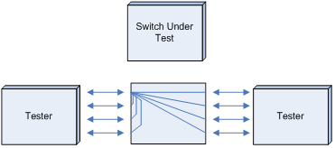
Fig 3. Partially Meshed Traffic: One to Many/Many to one.
Partially Meshed: Multiple Devices – In this traffic pattern two L2 switches are connected to each other by one high speed backbone link. Forwarding rates can be affected by the serialization time or packet transmission time per switch hop if the packets are stored several times between source and destination. If there are more than two devices connected in a bus configuration, serialization delay is incurred for every hop along the path.
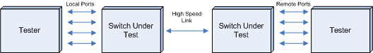
Fig 4. Partially Meshed Multiple Device Configuration with Two Switches Under Test
Partially Meshed: Unidirectional Traffic – This test determines how the L2 switch handles traffic in one direction from one half of the test ports destined to the other half of the test ports. This traffic pattern simulates a common network topology in which half of the users on a network are transmitting to each of the other half of users.
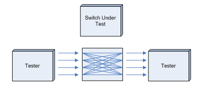
Fig 5. Partially Meshed Unidirectional Traffic
Congestion Control
To determine how a switch handles congestion, RFC2889 proposes tests to determine if the device implements congestion control mechanism and tests to find out if congestion on one port affects an uncongested port.
Consider two test ports transmitting at 100% wire rate. The two egress ports on the switch are receiving this traffic. One of these ports is uncongested, receiving 50% of the total 200% and the other is a congested port, receiving the remaining 150%.
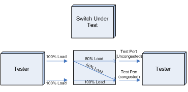
Fig 6. Congestion Control Traffic Pattern
Head of Line Blocking (HOLB) TEST – If a switch is losing frames destined for uncongested ports, it is said to have Head of line blocking (HOLB) present. If that is the case, frames are queued in a buffer at the input port or within the switching fabric. A frame destined for an uncongested output port can be forwarded only after all frames ahead of it in the queue are forwarded. This results in buffer overflow and frame loss for traffic streams forwarded over uncongested and congested ports. A switch without HOLB will not drop frames destined for uncongested ports, regardless of congestion on other ports. HOLB restricts the switch’s average forwarding performance.
Back Pressure TEST – Back pressure is defined in RFC 2285 as “any technique used by a switch under test to attempt to avoid frame loss by impeding external sources of traffic from transmitting frames to congested interfaces.” It is present if there is no loss on the congested port even with more than 100% load.
Some switches send jam signals back to traffic sources when their transmit or receive buffers start to overfill. Switches operating at full duplex traffic use 802.3X flow control or “Pause frame” for the same purpose. These flow control techniques prevent frames from being dropped but at the expense of available bandwidth on any network. Using flow control in even one switch of a network brings the performance of that network segment down to the speed of the slowest device currently using that switch. Extend this situation to a WAN with each switch using flow control and you’ve got problems!
Summary: Flow control and HOLB are really bad for a network.
Forward Pressure and Maximum Forwarding Rate
Forward pressure stresses the switch by sending it traffic at higher than wire rate load, using an interframe gap of 88 bits when the IEEE 802.3 standard allows for no less than 96 bits. The switch, on the egress port, should properly transmit per the standard with a 96-bit interfame gap. If the switch transmits at less than 96 bits, then forward pressure is detected.
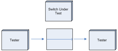
Fig 8. Unidirectional Traffic Pattern
Switches that transmit with less than a 96-bit interframe gap violate the IEEE 802.3 standard and gain an unfair advantage over other devices on the network. Other switches may not inter-operate properly with the switch in violation.
Maximum Forwarding Rate or MFR is simply the highest forwarding rate of a switch taken from iterations of forwarding rate measurement tests.
Address Caching Capacity
If you recall our last newsletter, when a switch tries to transmit frames with a MAC address not found in the MAC table, it “floods” the frames by broadcasting them to all ports on the switch (not just the intended port). This flooded traffic can have a devastating effect on the overall network resulting in dropped frames.
These tests provide insight on the maximum caching capacity of a switch’s forwarding table. It also provides means of measuring the number of addresses correctly learned by a switch.
In order to carry out such a test, the aging time of a switch must be known. Aging time is the maximum time a switch will keep a learned address in its MAC table. There should also be an initial number of addresses present in the MAC table to start the test with.
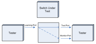
Fig 9. Address Caching Capacity/Learning Traffic Pattern – Frames to unlearned destinations are flooded to the Monitor Port
This test is performed in a minimum of three port configuration. One is a learning port, the second is a test port and the third being a monitor port.
The Learning Port (Lport) – Transmits learning frames to the switch with varying source addresses and a fixed destination address corresponding to the address of the device connected to the Test port (Tport) of the switch. By receiving frames with varying source addresses, the switch should learn these new addresses.
The Testing Port (Tport) – Acts as the receiving port for the learning frames. Test frames will be transmitted back to the addresses learned on the Learning port.
The Monitoring Port (Mport) – It listens for flooded or mis-forwarded frames. If the test spans multiple broadcast domains (VLANs), each broadcast domain REQUIRES a Monitoring port.
Address Learning Rate
This test determines the maximum rate, in frames per second, at which a layer 2 switch correctly learns MAC addresses. Learning frames will be sent at a given rate (fps) followed by test frames. The number of test frames received should be equal to the number sent without flooding. If flooding of the frames is received on a third port (the monitor port), or any other port, then the switch cannot handle the rate at which learning frames were sent. If no flooding of the frames occurs, then the test iteration is successful. The rate (fps) of learning frames can be increased for the next iteration.
Please note that the aging time of the switch MUST be known. The aging time MUST be longer than the time necessary to produce frames at the specified rate and the number of addresses should be equal to or less than the switch’s maximum address caching capacity.
Errored Frame Filtering
This test determines if a switch filters or forwards frames with errors. Now these errors can be of 5 different types and each of them are mentioned below:
- Oversized Frame – Frames larger than 1518 Bytes (or 1522 with VLAN tag) should not be forwarded by a switch.
- Undersized Frame – Frames smaller than 64 Bytes should be filtered.
- CRC Errored Frame – Frames that fail the frame check sequence should be filtered.
- Dribble Bit Errors – Dribble bits are frames without proper boundaries but contain valid FCS. These frames must be corrected and forwarded by the switch.
Alignment Errors – A frame with alignment error will have improper boundaries and an invalid FCS therefore it should be filtered by the switch.
These tests can be performed by forwarding errored frames to the switch and checking if the above is true for each illegal frame.
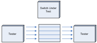
Fig 10. Errored Frame Port to port Traffic Pattern
Broadcast Frame Forwarding & Latency
This test will determine if the Layer 2 switch can handle broadcast traffic from one-to-many ports at various traffic loads. Broadcasts are necessary for a station to reach multiple stations with a single packet when the specific address of each intended recipient is not known by the sending node. Network traffic, such as some ARPs, are sent as broadcasts with a MAC destination address of all Fs. These broadcasts are intended to be received by every port on the switch. The performance of broadcast traffic on a switch may be different than the performance of unicast traffic. The throughput test will determine the maximum load at which the switch will forward Broadcast traffic without frame loss, as well as the latency of the traffic, for each of the recommended RFC 2889 frames sizes.
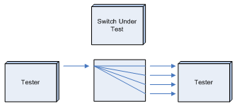
Fig 11. Broadcast Frame Forwarding & Latency Traffic Pattern
RFC2544 and RFC2899 based layer 2 switch tests are quite thorough but time consuming. The apparatus required to perform these tests is also quite expensive. It is just easier to ask questions from the network equipment manufacturers before finalizing a product.
Finally, a few simple things to keep in mind about an L2 switch are thait should meet industry standards for interoperability,
- it should not have head of line blocking,
- flow control should be disabled,
- it should have adequate address caching capacity to limit broadcasts intended for address learning &
- it should filter illegal frames.
Please let us know if we can assist you in your network design.