Ethernet networks have seen a phenomenal growth due to their ability to satisfy five critical requirements: performance (response time, bandwidth and scalability), resilience, ruggedness, economy, and interoperability. Due to this rapid growth, selecting optimal yet cost effective infrastructure components for a network from the litany of network equipment manufacturers and models available has become a daunting task even for seasoned systems engineers.
So what should be kept in mind while selecting and testing network components?
We are going to shed light on that in our upcoming editions but first let us have a look at the basics.
To give a brief introduction about Ethernet to our readers, it is an asynchronous, frame-based protocol originally intended to provide a means of communication between more than two data devices, using shared media. Ethernet, fully defined by the IEEE802.3 standard, has changed and evolved over time, increasing in speeds with full duplex transmission and extended link distances achievable using optical fiber as the transmission medium. The most common Ethernet physical interfaces in current use are:
- 10/100Base-T – 10Mbit/s or 100Mbit/s systems over twisted pair cable
- 100Base-Fx – 100Mbit/s over single mode or multimode optical fiber.
- 1000Base-T – 1000Mbit/s over twisted pair cable
- 1000Base-Sx – 1000Mbit/s over fiber @ 850nm over multimode fiber
- 1000Base-Lx – 1000Mbit/s over fiber @ 1310nm over singlemode or multimode fiber
Fiber has taken over as the preferred medium where required distances exceed 100m.
We will take a structured approach by looking first at an Ethernet frame and its constituent fields, then we will discuss Ethernet’s place in the OSI model, switching methodologies and finally the characteristics that should be tested to define the limits of a network. Here is a typical Ethernet frame:
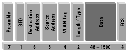
Figure 1: Structure of an Ethernet Frame
Preamble/Start of Frame Delimiter, 8 Bytes: These bytes allow for receiver Synchronization and mark the start of a frame.
Destination Address, 6 Bytes: Written usually in Hex, the MAC destination address of the frame is used to route it between devices.
Source Address, 6 Bytes: Mac address of the sending station. MAC address is often called a burnt-in address as these addresses are hard coded inside a network component at the time of manufacture. The first three bytes are also called Organizational Unique Identifiers (OUI) and as the name suggests, these identify the manufacturer. The remaining 3 Bytes are unique to the equipment.
VLAN Tag, 4 Bytes: This is optional. If a VLAN tag is present in the frame, it provides a means of separating data in to virtual LANs, irrespective of the MAC address. It also provides a priority tag which can be used to implement quality of service (QoS) functions.
Length/Type, 2 Bytes: This field determines either the length of the frame or type of data being carried in the data field (indication of the protocol carried by the data).
Data, 46-1500 Bytes: This is the data to be transported. It usually consists of higher layer protocols such as IP.
Frame Check Sequence, 4 Bytes: Using the information provided in this field, switches can detect if the full frame has been received. A frame gets dropped if it has incorrect or missing FCS.
The minimum legal frame size, including the FCS but excluding the preamble & VLAN tag, is 64 bytes. Frames below the minimum size are known as “runts” and would be discarded by most Ethernet equipment.
The maximum standard frame size is 1522 bytes if VLAN tagging is being used and 1518 bytes if VLAN is not being used. It is possible to use frames larger than the maximum size. Such frames are called “Jumbo frames” which have a better ratio of overhead bytes to data bytes but these are non-standard and manufacturer specific, therefore interoperability cannot be guaranteed.
Frames are transmitted from left to right (see Figure 1), least significant bit first. Frames are separated from each other by an Inter-packet gap. This is very useful for half-duplex operation where the medium has to go quiet before next frames starts transmission. Although not required for full duplex operation, it is still used for consistency. Minimum length of an inter-packet gap is 12 Bytes.
Ethernet & the OSI Model
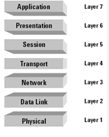
Figure 2: Seven layers of OSI Model
If you recall the OSI model and its seven layers, Ethernet covers the bottom two layers that are Layer 1 (Physical layer) and Layer 2 (Data link layer). Layer 1 simply consists of the physical medium (UTP or fiber) over which the data is transferred in the form of 1s and 0s and layer 2 provides the control mechanism for transmitting data on to the medium and receiving data from a medium. Network switches operate at these layers.
The function of Ethernet is to ensure that data is transferred over a single link in a communication network whereas layer 3 protocols ensure that the data is transferred from the original source to the destination using several Ethernet links (Figure 2). It is interesting to note that the popular “Ping” command is a layer 3 command which measures round trip time of a network packet and records any packet loss.
Higher layers have tasks of ensuring the integrity of transmitted data and its presentation to the user or application and are of little interest in a transmission environment.
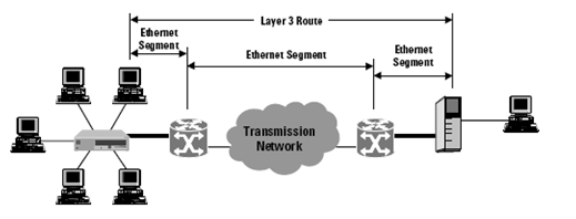
Figure 3 – A typical Network
The Ethernet Switch
Before we go in to the details of testing methodologies, let us have a look at a typical layer 2 switch. A layer 2 switch maintains a table of MAC addresses and looks this table up when it receives a frame. A switch chooses to do the following to the frame:
- Flood – If the destination MAC address is not in the MAC address table, the switch floods the frame which means it gets sent to all ports except for the port through which it arrived. Such a frame is called an unknown unicast frame. The destination MAC responds. The destination MAC address and the associated port are stored in the table.
- Filter – A frame will be discarded if the destination and source MAC addresses stored on the MAC address table are located on the same port.
- Forward – If the destination MAC address is in the MAC address table, the frame will be forwarded to the port to which the destination MAC address is connected.
Once the switch has decided to forward the frame, it uses one of the following three processes to do it.
Store and Forward – As the name suggests, the switch stores the entire frame and checks the FCS field for errors before forwarding the frame. By checking the FCS, this method gives a means for error detection. When a frame is found to have errors, it will be discarded.
Cut-through – The switch reads the destination MAC addresses and forwards the frame without storing it and without checking the FCS field. No error detection here but the fastest forwarding method. This method results in low switch latency. Both good and bad data frames get sent to destination ports.
Fragment Free – The switch stores first 64bytes of the incoming frame and if there is no error/corruption found in these bytes, it forwards the frame. It is a middle ground between store and forward and cut-through forwarding methods.
Switches also support auto-negotiation between each other to advertise their capabilities and configure themselves at the highest common setting. These capabilities include speed (10Mbits/s, 100Mbits/s & 1000Mbits/s), full or half duplex and the use of flow control.
OSD switches like the 4 port 10/100BaseT OSD2044 fiber optic switch utilizes the store and forward switching mechanism for greater error detection with ½ Megabit frame buffer memory. All OSD Ethernet modems come with a feature called auto MDI/MDIX which allows the user to connect the 10/100/1000BaseT ports on the OSD modems to any kind of Ethernet device without worrying about the type of Ethernet cable (straight-through or cross-over) being used for the connection.
Testing Ethernet Services
Ethernet connections must be tested to ensure correct operation at the required levels of traffic. The procedures for performing these tests & specifications for frame sizes, test durations and number of test iterations have been detailed by the IETF and documented in RFCs (Requests for Comments, which are technical proposals and/or documentation). The most relevant RFCs for testing network equipment are RFC2544 (Benchmarking Methodology for Network Interconnect Devices) and RFC2889 (Benchmarking Methodology for LAN Switching Devices).
While RFC2544 is written as a general methodology for networking devices of all types, RFC2889 is written specifically to benchmark the performance of a layer 2 LAN switching device.
In this newsletter, we will discuss RFC2544 and some of the tests it outlines and building on this information, we will look at RFC2889 in our next newsletter.
Frame Sizes – In order to ensure that an Ethernet network is capable of supporting a variety of services (such as VoIP, video, etc.), both RFC 2544 & RFC 2889 support seven pre-defined frame sizes (64, 128, 256, 512, 1024, 1280 and 1518 bytes & 1522 bytes including VLAN) to simulate various traffic conditions. Small frame sizes increase the number of frames transmitted, thereby stressing the network device as it must switch a large number of frames.
RFC 2544 Tests 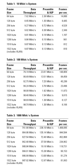
Throughput – Data throughput is simply the maximum amount of data that can be transported from source to destination. A throughput test defines the maximum number of frames per second that can be transmitted without any error. This test is done to measure the rate-limiting capability of an Ethernet switch.
The maximum throughput achievable for various frame sizes is given in tables 1, 2 and 3 or 10, 100 and 1000Mbit/s respectively. IGP stands for the inter-packet gap and a minimum size of 12Bytes has been used.
Back-to-Back – The back-to-back test (also known as burstability or burst test) assesses the buffering capability of a switch. Back-to-back frame testing involves sending a burst of frames with minimum inter-frame gaps to the device under test (DUT) and count the number of frames forwarded by the DUT. If the count of transmitted frames is equal to the number of frames forwarded the length of the burst is increased and the test is rerun. If a frame is lost, burst length is shortened.
Frame Loss Test – The frame loss test measures the network’s response in overload conditions—a critical indicator of the network’s ability to support real-time applications in which a large amount of frame loss will rapidly degrade service quality. As there is no re-transmission in real-time applications, these services might rapidly become unusable if frame loss is not controlled.
For example, 1000 frames are transmitted but only 950 were received the frame loss rate would be: (1000 – 950) / 1000 x 100% = 5%. Frames can be lost, or dropped, for a number of reasons including errors caused by incorrect FCS, excessive delay in reception of frames etc.
Latency Test – The latency test measures the time required for a frame to travel from the originating device through the network to the destination device (also known as end-to-end testing). This test can also be configured to measure the round-trip time; i.e., the time required for a frame to travel from the originating device to the destination device and then back to the originating device.
System Reset Test – The objective of the test is to characterize the speed at which a DUT recovers from a device or software reset. Both hardware & software resets should be tested and results should be recorded in a simple set of statements for each type of reset.
System Recovery Test – This test checks the speed at which a DUT recovers from an overload condition. It is performed by sending a stream of frames at a rate 110% of the recorded throughput rate for at least 60 seconds, stressing the DUT with high traffic. At time stamp A, frame rate is reduced to 50 % of the above rate and time of the last frame that was lost due to high traffic is recorded (time stamp B). The system recovery time is determined by subtracting time stamp B from time stamp A.
RFC 2544 primarily describes non-meshed traffic which means that the test frames are offered to a single port and addressed to a single output port on a switch under test for both uni-directional and bi-directional traffic. RFC2889 on the other hand provides methodology for testing switches with partially meshed and fully meshed traffic patterns. In a fully meshed pattern all ports offer traffic destined to all other ports on a switch under test whereas in partially meshed traffic scenario, one test port send traffic to many ports and vice versa.
More comprehensive tests are outlined in RFC2889 which provides methodology for testing switches with partially meshed and fully meshed traffic patterns.
Partially meshed traffic pattern means that frames are offered to one or more input interfaces of a switch and addressed to one or more output interfaces where input and output interfaces are mutually exclusive and mapped one-to-many, many- to-one or many-to-many.
Fully Meshed Traffic pattern means that frames are offered to a designated number of interfaces of a switch such that each one of the interfaces under test receives frames addressed to all of the other interfaces under test.
This is to be continued in our next newsletter….
Don’t hesitate to contact OSD Systems Engineers for any further information on this subject.