

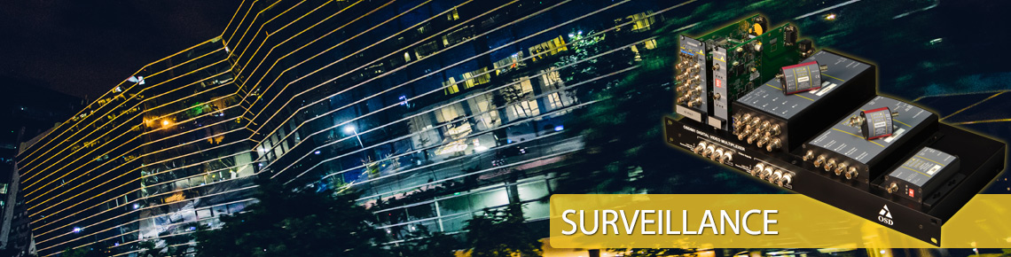
Frequently Asked Questions
Questions: (Please click on a question to link to the answer)
- Why use fiber optics?
- How do fibers work?
- What is the difference between multimode and singlemode?
- What transmission loss can be expected when using optical fiber cable?
- What is the maximum distance that a fiber optic modem can go?
- How do I calculate link budgets?
- What are the comparative advantages of AM, FM and Digital video transmission technologies?
Answers:
- Immunity to electrical interference, ground loops and short circuits
- Does not cause electrical interference
- Practically inexhaustible transmission capacity
- Much lower loss and higher bandwidth than copper
- Very secure transmission
- Cost effective for longer distances
The fibers used in communications consist of a hair thin strand of glass coated with a plastic coating for mechanical protection. The actual glass strand is actually made up of two components: a core of between 9 and 62.5μm in diameter surrounded by a cladding of lower refractive index glass with an outside diameter of 125μm. There are other types of fiber both in terms of materials used and dimensions but the ones mentioned are by far the most common. Light travels in the core region by “Total Internal Reflection” which means that light rays bounce off the core cladding interface and make their way from the input of the fiber to the other end. A fiber with a 62.5 μm core and 125μm cladding diameter is referred to as a 62.5/125μm fiber.
3. What is the difference between multimode and singlemode?
Almost all multimode fiber is 50/125μm or 62.5/125μm in size and typically has a bandwidth (the fiber’s information carrying capacity) of from 200MHz to 2GHz. Multimode modems usually operate up to about 5km on a multimode fiber. Singlemode fiber is 9-10/125μm and has practically unlimited bandwidth and lower loss than multimode. Singlemode modems are usually used for longer distances, sometimes to as much as 150 to 200km. Singlemode fiber is cheaper to buy, but singlemode equipment is more expensive than the multimode equivalent. Singlemode equipment will often operate on multimode fiber as well as singlemode, whereas multimode equipment operates only on multimode fiber.
4. What transmission loss can be expected when using optical fiber cable?
This depends on the wavelength used to transmit the information as well as the type of fiber used.
- Multimode Optical Fiber @ 850nm : Typically 3.0dB/km
- Multimode Optical Fiber @ 1310nm : Typically 1.0dB/km
- Singlemode Optical Fiber @ 1310nm : Typically 0.4dB/km
- Singlemode Optical Fiber @ 1550nm : Typically 0.2 dB/km
5. What is the maximum distance that a fiber optic modem can go?
The maximum distance a modem can go is the difference between receiver sensitivity and transmit power of the fiber optic modems (which can both be found on OSD data sheets) divided by the transmission loss of the fiber used. For example, a basic singlemode OSD815 digital video system’s transmitter power is greater than -10dBm and its receiver sensitivity is better than -29dBm so the difference of 19dB at 1310nm allows operation over at least 45km. Note this would be very poor design because there is no allowance for a link margin.
6. How do I calculate link budgets?
The difference between transmitter power and receiver sensitivity is eaten up by:
- Fiber losses
- Connector losses (eg, at patch panels)
- Splice losses
- Link margin
The link margin can be as low as 2 or 3dB in very well engineered and controlled environments and as much as 10dB in some situations. It is intended to allow for:
- Component aging (eg, some light sources’ lifetimes are specified for when their power drops by half, ie 3dB)
- Temperature effects on both transmitters and receivers (it may be necessary to allow 3dB or so for transmitter power variations with at temperature range extremes)
- Possible damage to cables and consequent extra losses due to repairs (this is usually negligible but in some industrial situations it may be possible for cable damage to occasionally occur)
- Always design your system on a “worst case” basis but also make sure it will operate in a “best case” situation: sometimes optical receivers misbehave if they get too much power!
7. What are the comparative advantages of AM, FM and Digital video transmission technologies?
There is some confusion in the marketplace as which technology is most appropriate for different applications. While there is a lot of marketing hype about digital technology the fact remains that for many applications AM offers very adequate performance at extremely competitive pricing. The following attempts to give a flavour of the trade offs between the main technologies available today. Please contact us if you need any technical advice.
AM
AM is very simple technology which can provide extremely good performance for many situations. It is easy to get wide bandwidths (at least 15MHz for our OSD381/383 pair, much more for some specialty products) without excessive circuit complexity. Also, over low optical loss budgets typical of most security type CCTV which only occasionally operates over more than 2 to 3km, the signal-to-noise ratio attainable with AM can be very good. This does degrade from some maximum value (typically 55 to 70dB measured over a short fiber length) with increasing fiber length (and loss), so some care is required to ensure that your optical loss budget is under control. However, linearity as measured by parameters such as differential gain and phase, while perfectly adequate for single hop CCTV links is not usually good enough for systems where 3 or 4 links may have to be put in for the series. It can be difficult to achieve the linearity obtained with multimode AM systems on singlemode AM links because the optical devices required for the latter are usually not as linear as those for multimode.
FM
FM has two key advantages over AM.
- Performance is not so strongly dependent on optical loss: the signal to noise ratio will degrade slowly with increasing loss to a threshold point after which it degrades very quickly.
- Performance is not dependant on the linearity of the optical components since it is almost completely dominated by the FM modulator and demodulator.
This improvement comes at a small cost of an increase in circuit complexity and cost and a large increase in fiber bandwidth required. Generally the latter is not too critical but must be factored in if you are considering long runs on multimode fiber (eg greater than 10 to 20km) due to modal bandwidth limitations or even longer runs on singlemode fiber (eg greater than 30 to 100km) due to material dispersion effects. OSD’s application engineers can advise on the best design choices in these cases.
Typically FM systems offer good SNR (60 to 65dB) which is maintained over substantial optical losses and good linearity which is typically 2 to 3 times better than AM. Consequently, multiple loops become more practical.
DIGITAL
Digital system video performance is dominated by the analog to digital conversion at the transmit end and the digital to analog conversion at the receive end. The actual transmission path will have virtually no visual effect on the picture if the Bit Error Rate is better than 1 error in 1 billion bits (ie a BER of 1 X 10⁻⁹). In fact, BERs down to as low as 1 X 10⁻⁴ still allow quite useable signals to be received and monitored on screens.
These excellent characteristics come at the cost of:
- Increased circuit complexity and cost.
- Greatly increased transmission bandwidth requirements.
The basic SNR is determined by the number of quantization levels, which are in turn fixed by the number of bits per digital word. Typically systems use between 8 and 12 bits leading to weighted SNR values of between about 56dB for 8bits and >70dB for 12 bits.
Be careful about the headroom allowed in digital systems: typically if you exceed the nominal level of AM and FM systems some distortion takes place but it may not be obvious. Exceeding the limit in a digital system results in fairly obvious limiting effects. Unlike its competitors, OSD includes an extra 3dB headroom in its input circuits to allow for out-of-specification cameras, matrix switches and distribution amplifiers which are often exist in the real world. We achieve this by using AD converters which are specified at a very high level: for example our 10 bit products all use 12 bit AD convertors, even though we only transmit 10 bits over the fiber, to ensure true 10 bit performance.
As noted earlier, digital systems require far more bandwidth than FM or AM systems. For example, OSD’s 4 channel OSD870, 880 and 890 systems offer studio quality 10MHz video performance and operate on the fiber at 1.35Gbps. This significantly reduces the distances achievable in multimode fiber: contact OSD Application Engineering for advice when using multimode or when transmitting more than 50km on singlemode fiber.
SUMMARY
For many simple applications consider AM for its good performance at cost effective pricing. Also consider AM where long lengths of multimode cable must be covered.
Most commercial and professional applications are well served by FM based systems which offer excellent video, audio and data performance.
Finally, where extremely high performance is essential all digital systems are the preferred choice but do be careful about their operation over multimode fiber.