Fiber equipment suppliers often use two optical wavelengths to enable bidirectional transmission over the one fiber, usually 1310 and 1550nm on singlemode and 850 and 1310nm on multimode. See “Fiber Operating Wavelengths Why so many” for more background information on this. In actual fact, fiber can carry many more than just one or two wavelengths and that some telecommunications systems employ well over a hundred on the one fiber.
Why is this done? As with most things it comes down to costs. When transmission distances start climbing beyond hundreds of kilometers a major cost in the system is that of repeating the optical signals every 50 to 150km. With conventional systems with one electrical signal per fiber this adds enormously to the cost because each signal requires a receiver, regenerator and transmitter. Added to that are the associated costs of installation, maintenance, powering, etc. Even if many signals were to be somehow accommodated on the one fiber (thus saving fiber costs) there would still be the considerable costs of all these electronic modules. One solution might be to avoid the whole business of converting from light to electrical, regeneration then electrical to optical by directly amplifying the light signal(s) at the repeater sites. The Erbium Doped Fiber Amplifier (EDFA) was invented in the late 1980s to do just this and within a few years of its invention was being widely deployed in terrestrial and submarine systems operating over thousands of kilometers. However, the EDFA can only amplify a relatively narrow spectrum of signals, typically about 30 to 50 nm centered on 1550nm so it is essential if it is to be used effectively to channel as many wavelengths through the fiber as possible within that range. Systems exploiting the EDFA have been developed and are often described as Dense Wavelength Division Multiplexing (DWDM). Typical spacings are 200GHz (wavelength separation of about 1.6nm allowing around 25 channels), 100GHz (0.8nm, 50 channels) and 50GHz (0.4nm, 100 channels). As you would expect, the costs of the precision lasers and optical multiplexers and demultiplexers increases with lower channel separation/increasing channel capacity.
Other techniques are becoming more available for field use that extend the optical wavelength range so that systems carrying 160 or even more separate optical signals are now practical.
All of which is great if you need to provide a backbone for a major telecommunications system extending over thousands of kilometers but may be of academic interest only to an operator of infrastructure such as railways or highways.
The good news for such folk is that much of the technology originally developed for the bleeding edge of telecommunications is now available in simplified and vastly less expensive form under the umbrella term Coarse Wavelength Division Multiplexing (CWDM).
Originally, CWDM was intended only for the 8 wavelengths between 1470 and 1610nm on 20nm spacings because operation with many older fibers from around 1350 to 1450nm was a bit questionable due to their poor attenuation characteristics in this region. However, modern fibers exhibit little or none of the “water peak” that was the cause of this poor attenuation so it is now quite practical to use 18 wavelengths from 1271 to 1611nm. (Please refer to Tech Note “Fiber Operating Wavelengths Why so many” for a sketch of the typical characteristics of older fibers).
CWDM uses similar basic lasers as DWDM but they usually operate at lower powers and without the temperature controllers essential for DWDM so are far lower cost. Likewise, CWDM optical muliplexers and demultiplexers are of far less precision so are well suited to typical industrial and commercial applications.
Where are these things used?
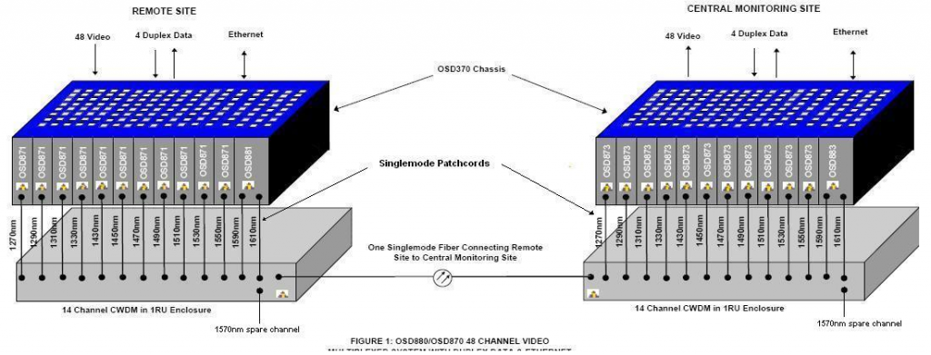
Mostly, the technology is used simply to increase raw fiber capacity. For example, a few years ago OSD supplied a very high end surveillance system operating over 10 to 30km with 48 broadcast quality point to point uncompressed digital video links based on our OSD870 and OSD880 4-channel video multiplexers. This required 13 CWDM channels, 12 for the video and 1 for the reverse data control signals as shown in the sketch below.
However, CWDM can provide some other really useful features that go way beyond just adding capacity as shown in Tech Note “More on CWDM” which describes a further two CWDM systems, one in China and the other in Australia.


